
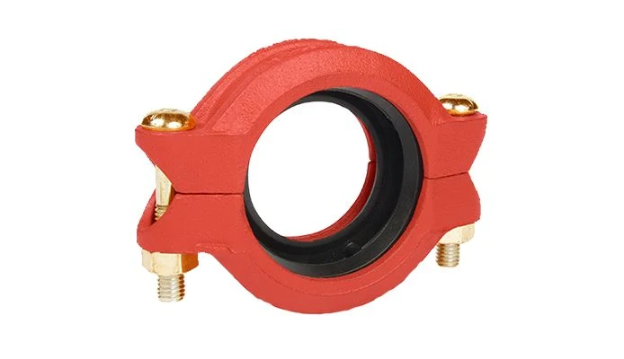
Product overview
The GRINNELL Figure 716 – Flexible Reducing Coupling range is used to connect two different compatible pipe sizes using a reducing flexible coupling. It belongs to the manufacturer's G-Fire pipe-joining portfolio. The published reference identifies the product arrangement and available selection information; it is not a substitute for the exact size and configuration required by the project. Review the listed technical data and confirm the pipe, connection and gasket combination before procurement.
Technical specifications
| Manufacturer | Johnson Controls |
|---|---|
| Brand / product range | GRINNELL |
| Product / system | Figure 716 Flexible Reducing Coupling |
| Product type | Water-Based Systems |
| Product family | Grooved Piping |
| Subcategory | Fire Grooved |
| Product Type | Flexible Coupling |
| Sizes | 2 inch x 1 ½ inch (DN50 x DN40) to 8 inch x 6 inch (DN200 x DN150) |
| Finish | Orange, non-lead paint; RAL, red non-lead paint; hot-dipped galvanized conforming to ASTM A153 |
| Application restriction | The manufacturer does not recommend this reducing coupling for low-temperature applications. |
| Selection basis | Exact model, size, pipe wall, groove and gasket compatibility must follow the selected manufacturer technical documentation. |
Key features
- Connection function: Connect two different compatible pipe sizes using a reducing flexible coupling
- Manufacturer range: Grinnell G-Fire
- Product-specific manufacturer reference for equipment selection
Applications
Compatible fire protection piping systems within the selected manufacturer's documented model, size and operating conditions. The connection arrangement and acceptance requirements must be confirmed for the project.
Selection and project integration
Share the system drawings, protected hazard, equipment schedule and project specification with UDCT. Product selection should establish the required flow and pressure, pipework connections, materials, installation orientation and compatible components. Check the precise approval scope for the selected model, size and configuration against the current manufacturer documentation.
The product reference does not replace hydraulic calculations or the approved system design. For foam equipment, confirm the concentrate, proportioning range and discharge-device compatibility as one system. Use the manufacturer instructions for installation, commissioning and maintenance, and confirm the supplied configuration with UDCT before procurement.
Manufacturer documents
- IH-1000FP Installation Handbook (opens in a new tab)
- TFP1830 Technical Data Sheet (opens in a new tab)
- TFP1895 Technical Data Sheet for Gaskets (opens in a new tab)
- TFP1898 Fire Grooved Specifications (opens in a new tab)
Official product reference
View this product on the manufacturer website (opens in a new tab)