
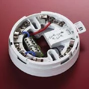
Product overview
This VES range provides mounting and addressing accessories for compatible Apollo-protocol sensors. Standard bases provide the mechanical and electrical connection, while the relay base adds a detector-controlled voltage-free interface. The XPERT card holds the location address in the base rather than the replaceable sensor head. Choose the exact base, detector and required retention features as a documented combination; accessories with different functions must not be substituted by size alone.
Technical specifications
| Brand / product range | VES |
|---|---|
| Product / system | Apollo Sensor Bases |
| Product type | Fire Detection |
| Product family | Fire Detection & Alarm |
| Subcategory | Apollo Addressable |
| Product range | Sensor mounting bases and XPERT address accessories |
| VF5630-00 | 4 inch mounting base |
| VF5636-00 | 6 inch mounting base |
| VF5635-00 | Low-power relay base; detector remote output controls voltage-free contacts |
| VF5632-00 | 6 inch low-profile E-Z Fit base for compatible ACC sensors |
| VF5640-00 | Blank XPERT address card |
| Mounting-base contacts | Stainless steel; low insertion force |
| Address arrangement | XPERT card retains the location address when the compatible sensor head is replaced |
| Retention | One-way fit and locking provisions, according to base version |
| Compatibility | Select the exact detector/base combination from current manufacturer instructions |
| Selection note | The model descriptions follow the dedicated Sensor Bases sheet; other sensor sheets use inconsistent accessory descriptions |
Key features
- Product range: Sensor mounting bases and XPERT address accessories
- VF5630-00: 4 inch mounting base
- VF5636-00: 6 inch mounting base
Applications
Installation, replacement and maintenance of compatible addressable sensor heads where the approved equipment schedule specifies the corresponding mounting, relay and addressing accessories.
Selection and project integration
Share the fire alarm drawings, equipment schedule, compatible panel platform and cause-and-effect requirements with UDCT. Selection should confirm device protocols, supported interfaces, circuit supervision, power and standby calculations, and the exact enclosure or module arrangement.
Use the current manufacturer documentation to check compatibility, wiring limits, software requirements and approval scope. Commissioning should verify the configured alarm, fault, indication and control functions as part of the complete system. Remote reporting also requires a compatible receiving service and confirmation of local network availability.
Manufacturer documents
Official product reference
View this product on the manufacturer website (opens in a new tab)