
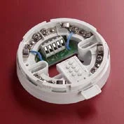
Product overview
The VES SLC isolator range limits the part of a compatible signalling loop affected by a short circuit. It includes an isolating sensor base and a separate isolator with its dedicated mounting base. Once the fault is removed, the documented isolator automatically restores power and data to the affected section. Isolation does not preserve service to every device inside the isolated segment, so layout and device grouping remain part of the approved system design.
Technical specifications
| Brand / product range | VES |
|---|---|
| Product / system | Apollo SLC Isolators |
| Product type | Fire Detection |
| Product family | Fire Detection & Alarm |
| Subcategory | Apollo Addressable |
| Range components | VF5633-00 isolating base; VF5605-00 isolator; VF5634-00 dedicated isolator base |
| VF5633 function | Detects short-circuit faults on compatible SLC loops |
| VF5633 addressing | XPERT addressing |
| VF5605 function | Isolates a short-circuited loop section between isolators |
| Restoration | Automatic power and data restoration when the short circuit is removed |
| Published spacing limit | Up to 20 devices between isolators or isolating bases; confirm topology and current installation instructions |
| VF5634 compatibility | Accepts the isolator only; it is not a general sensor mounting base |
| Design coordination | Place isolation boundaries according to the panel instructions and required fault-containment strategy |
Key features
- Range components: VF5633-00 isolating base; VF5605-00 isolator; VF5634-00 dedicated isolator base
- VF5633 function: Detects short-circuit faults on compatible SLC loops
- VF5633 addressing: XPERT addressing
Applications
Fault containment on compatible addressable fire alarm loops, with isolation boundaries and the number of devices per section established by the manufacturer wiring instructions.
Selection and project integration
Share the fire alarm drawings, equipment schedule, compatible panel platform and cause-and-effect requirements with UDCT. Selection should confirm device protocols, supported interfaces, circuit supervision, power and standby calculations, and the exact enclosure or module arrangement.
Use the current manufacturer documentation to check compatibility, wiring limits, software requirements and approval scope. Commissioning should verify the configured alarm, fault, indication and control functions as part of the complete system. Remote reporting also requires a compatible receiving service and confirmation of local network availability.
Manufacturer documents
Official product reference
View this product on the manufacturer website (opens in a new tab)