
Product overview
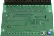
The VES Elite XT Ancillary PCB provides voltage-free normally open relay contacts for compatible remote plant and subsystem interfaces. It connects to the panel using serial data and power wiring, with each board assigned a supported address. The bare board and boxed versions have different physical arrangements, so enclosure, supply, contact load and cable limits must be checked for the selected installation.
Technical specifications
| Manufacturer | Kentec Electronics Ltd. |
|---|---|
| Brand / product range | VES |
| Product / system | Elite XT Ancillary PCB |
| Product type | Fire Detection |
| Product family | Releasing & Control |
| Subcategory | Releasing |
| Models | VF1822-00 board / VF1822-10 red cabinet / VF1822-40 gray cabinet |
| Compatible platform | Elite XT |
| Supply range | 20–30 V DC |
| Contacts | Voltage-free normally open contacts, rated 1 A at 30 V DC |
| Interface | Two-wire serial data plus two-wire power |
| Maximum ancillary boards | Seven, addresses one through seven |
| Maximum data cable length | 4,000 ft from panel to last device, manufacturer conditions apply |
| PCB dimensions W x H | 6.1 x 5.35 inches |
| Boxed dimensions W x H x D | 15.1 x 12.2 x 3.54 inches |
| Box construction | 18 gauge mild steel |
| Operating temperature | 23°F to 122°F |
| Humidity | Less than 95%, non-condensing |
Key features
- Models: VF1822-00 board / VF1822-10 red cabinet / VF1822-40 gray cabinet
- Compatible platform: Elite XT
- Supply range: 20–30 V DC
Applications
Remote signalling and approved ancillary plant interfaces within a compatible Elite XT releasing-control installation.
Selection and project integration
Share the fire alarm drawings, equipment schedule, compatible panel platform and cause-and-effect requirements with UDCT. Selection should confirm device protocols, supported interfaces, circuit supervision, power and standby calculations, and the exact enclosure or module arrangement.
Use the current manufacturer documentation to check compatibility, wiring limits, software requirements and approval scope. Commissioning should verify the configured alarm, fault, indication and control functions as part of the complete system. Remote reporting also requires a compatible receiving service and confirmation of local network availability.
Manufacturer documents
Official product reference
View this product on the manufacturer website (opens in a new tab)