
Product overview
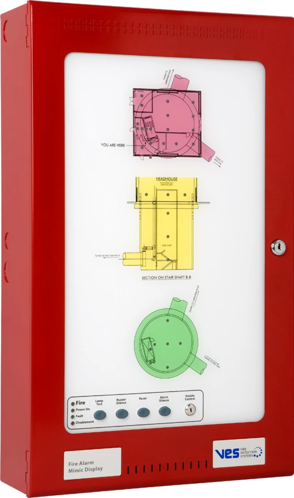
The VES eMATRIX is a configurable floor-plan mimic annunciator for compatible Elite fire alarm systems. Flexible optical light guides connect the selected indicator positions to an internal LED grid, allowing the display layout to be adapted without individual wiring to every indicator. The floor plan, enclosure, LED count and optional controls are specified together for the installation.
Technical specifications
| Manufacturer | Kentec Electronics Ltd. |
|---|---|
| Brand / product range | VES |
| Product / system | eMATRIX Configurable Floor Plan Mimic Annunciator |
| Product type | Fire Detection |
| Product family | Fire Detection & Alarm |
| Subcategory | Addressable Control Panels / Network |
| Model families | VF130X-YYY / VF132X-YYY / VF133X-YYY; enclosure and LED-board options selected separately |
| Supply voltage | 21–30 V DC |
| Communication | RS485, Elite serial I/O bus protocol |
| Maximum system indicators | Up to 504 LEDs controlled from an Elite panel |
| Standard enclosure capacities | AM2: 40 LEDs / AM3: 72 LEDs / AM4: 88 LEDs |
| LED colours | Red / green / yellow |
| Enclosure construction | 16 gauge mild steel, epoxy powder coating |
| Mimic surface | 3 mm clear anti-glare acrylic |
| Enclosure rating | IP30 |
| Maximum panel distance | 4,000 ft using the specified RS485 data cable |
| Operating temperature | 20°F to 120°F |
| Manufacturer-listed approvals | UL 864, 9th edition; confirm current configuration listing |
Manufacturer technical data
| Enclosure | Dimensions W x H x D | Maximum LEDs |
|---|---|---|
| AM2 | 14.5 x 12.2 x 3.5 inches | 40 |
| AM3 | 14.5 x 18.9 x 4.25 inches | 72 |
| AM4 | 14.5 x 24 x 5 inches | 88 |
Approval scope applies to the listed system and component configuration. Confirm the selected equipment against the current manufacturer document and project submittal.
Key features
- Model families: VF130X-YYY / VF132X-YYY / VF133X-YYY; enclosure and LED-board options selected separately
- Supply voltage: 21–30 V DC
- Communication: RS485, Elite serial I/O bus protocol
Applications
Geographical fire alarm indication at reception, control and monitoring locations where a floor-plan display helps identify the activated area.
Selection and project integration
Share the fire alarm drawings, equipment schedule, compatible panel platform and cause-and-effect requirements with UDCT. Selection should confirm device protocols, supported interfaces, circuit supervision, power and standby calculations, and the exact enclosure or module arrangement.
Use the current manufacturer documentation to check compatibility, wiring limits, software requirements and approval scope. Commissioning should verify the configured alarm, fault, indication and control functions as part of the complete system. Remote reporting also requires a compatible receiving service and confirmation of local network availability.
Manufacturer documents
Official product reference
View this product on the manufacturer website (opens in a new tab)