
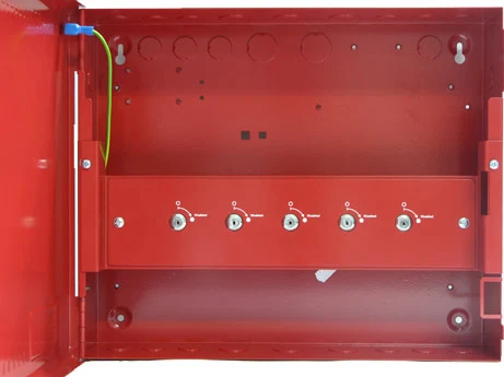
Product overview
The VES VF0716-X0 Disablement Switch Enclosure provides five key switches for configured system functions in an organised enclosure. The selected model determines enclosure depth, mounting arrangement and any tamper option. Coordinate the supplied enclosure and its contents with the equipment schedule, access needs and installation location. Modules, assigned switch functions and other optional components must be confirmed separately where applicable.
Technical specifications
| Brand / product range | VES |
|---|---|
| Product / system | VF0716-X0 Disablement Switch Enclosure |
| Product type | Fire Detection |
| Product family | Accessories & Power |
| Subcategory | Accessories / Power |
| Model | VF0716-X0 |
| Function | Enclosure with five individual key switches |
| Configured actions | Pre-programmed disablements or other compatible system functions |
| Connections | Terminal strip behind each key switch |
| Dimensions W x H x D | 14.5 x 12.2 x 3.4 inches |
| Construction | 18 gauge sheet steel |
| Weight | 6.6 lb |
| Colours | Red suffix -10 / gray suffix -40 |
| Selection | Confirm supported panel interfaces, assigned functions and electrical ratings in current documentation |
Key features
- Model: VF0716-X0
- Function: Enclosure with five individual key switches
- Configured actions: Pre-programmed disablements or other compatible system functions
Applications
Controlled activation of the pre-programmed functions supported by the selected fire alarm system and approved operating procedures.
Selection and project integration
Share the fire alarm drawings, equipment schedule, compatible panel platform and cause-and-effect requirements with UDCT. Selection should confirm device protocols, supported interfaces, circuit supervision, power and standby calculations, and the exact enclosure or module arrangement.
Use the current manufacturer documentation to check compatibility, wiring limits, software requirements and approval scope. Commissioning should verify the configured alarm, fault, indication and control functions as part of the complete system. Remote reporting also requires a compatible receiving service and confirmation of local network availability.
Manufacturer documents
Official product reference
View this product on the manufacturer website (opens in a new tab)