
Product overview
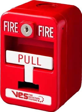
The VES VF3033 and VF3034 provide single-action and dual-action manual alarm initiation for a compatible Apollo XP95 installation. The handle latches visibly after operation and is returned to its normal position using the station key. The specified contact module provides the addressable connection and supervises the field contact wiring. Confirm the station, module and backbox as a complete assembly, especially where an enclosure suitable for the installation environment is required.
Technical specifications
| Brand / product range | VES |
|---|---|
| Product / system | VF3033 / VF3034 Pull Stations |
| Product type | Fire Detection |
| Product family | Fire Detection & Alarm |
| Subcategory | Apollo Addressable |
| Models | VF3033-10 single action / VF3034-10 dual action |
| Communication | Apollo XP95 digital communications |
| Addressable interface | VF5608-00 contact module, as listed in the ordering table; confirm the supplied assembly |
| Loop voltage | 17–28 V DC |
| Average current | 200 µA |
| Alarm current | 3.6 mA |
| Alarm contact rating | 1 A at 30 V DC |
| Reset | Key reset |
| Installation temperature | 32°F to 100°F |
| Humidity | Up to 90% RH, non-condensing |
| Dimensions H x W x D | 4.75 x 3.25 x 1.1 inches |
| Station weight | 1.2 lb |
| Mounting | Single-gang backbox, VF3007-10 surface backbox or specified VF3008-10 weatherproof assembly |
| Supplied items in referenced sheet | One scored acrylic breakrod and one key |
Key features
- Models: VF3033-10 single action / VF3034-10 dual action
- Communication: Apollo XP95 digital communications
- Addressable interface: VF5608-00 contact module, as listed in the ordering table; confirm the supplied assembly
Applications
Manual fire alarm initiation at designated accessible locations in a compatible addressable system. Select action type, reset arrangement and mounting enclosure to match the approved project schedule.
Selection and project integration
Share the fire alarm drawings, equipment schedule, compatible panel platform and cause-and-effect requirements with UDCT. Selection should confirm device protocols, supported interfaces, circuit supervision, power and standby calculations, and the exact enclosure or module arrangement.
Use the current manufacturer documentation to check compatibility, wiring limits, software requirements and approval scope. Commissioning should verify the configured alarm, fault, indication and control functions as part of the complete system. Remote reporting also requires a compatible receiving service and confirmation of local network availability.
Manufacturer documents
Official product reference
View this product on the manufacturer website (opens in a new tab)