
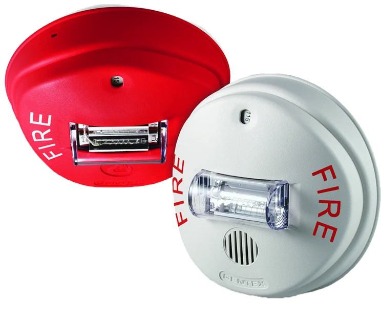
Product overview
The VES VF4003-X0 Ceiling Strobe is an indoor ceiling-mounted strobe without a horn. Select the exact mounting format and supported output settings for the approved notification design. The supply waveform, selected sound pattern or candela setting, synchronization interface and circuit load determine the permitted installation. This product is not presented as an outdoor appliance.
Technical specifications
| Brand / product range | VES |
|---|---|
| Product / system | VF4003-X0 Ceiling Strobe |
| Product type | Fire Detection |
| Product family | Notification Appliances |
| Subcategory | Notification |
| Models | VF4003-10 red / VF4003-30 off-white |
| Appliance | Ceiling-mounted strobe, without horn |
| Nominal supply / operating range | 24 V DC / 16–33 V DC or documented FWR supply |
| Candela settings | 15 / 30 / 75 / 95 / 115 / 150 cd |
| Minimum flash rate | 1 Hz, according to sheet |
| Dimensions | 6 inch diameter x 2.6 inch depth |
| Terminals | 12–18 AWG |
| Operating temperature | 0°C to +49°C |
| Environment | Indoor only; not listed for outdoor use |
| Circuit selection | No coded / pulsing signalling circuit, according to manufacturer guidance |
| Manufacturer-listed approvals | UL 1971 / FM scope for exact ceiling strobe must be confirmed |
| Current table scope | Strobe load only; combined models also require the configured horn load. FWR and nominal/peak values require the manufacturer installation manual. |
Manufacturer technical data
| Strobe current only / candela | 15 | 30 | 75 | 95 | 115 | 150 |
|---|---|---|---|---|---|---|
| At 24 V DC, mA | 72 | 101 | 167 | 200 | 214 | 286 |
| Manufacturer UL maximum RMS, mA | 120 | 130 | 247 | 318 | 360 | 454 |
Approval scope applies to the listed system and component configuration. Confirm the selected equipment against the current manufacturer document and project submittal.
Key features
- Models: VF4003-10 red / VF4003-30 off-white
- Appliance: Ceiling-mounted strobe, without horn
- Nominal supply / operating range: 24 V DC / 16–33 V DC or documented FWR supply
Applications
Indoor fire alarm notification within the exact model listing, with sound or visual coverage, accessibility requirements, synchronization and circuit power calculated for the project.
Selection and project integration
Share the fire alarm drawings, equipment schedule, compatible panel platform and cause-and-effect requirements with UDCT. Selection should confirm device protocols, supported interfaces, circuit supervision, power and standby calculations, and the exact enclosure or module arrangement.
Use the current manufacturer documentation to check compatibility, wiring limits, software requirements and approval scope. Commissioning should verify the configured alarm, fault, indication and control functions as part of the complete system. Remote reporting also requires a compatible receiving service and confirmation of local network availability.
Manufacturer documents
Official product reference
View this product on the manufacturer website (opens in a new tab)