
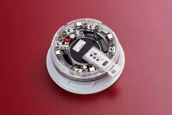
Product overview
The VES VF5651 XP95A sounder beacon base combines local audible and visual alarm indication with a compatible sensor mounting arrangement. It is loop powered and individually addressed, with synchronized tones and flash operation. The beacon follows the sounder and is not independently switched. A detector or a suitable cap is selected according to the installation; verify the exact panel protocol, loop loading and supported control functions before specifying the assembly.
Technical specifications
| Brand / product range | VES |
|---|---|
| Product / system | VF5651 XP95A Sounder Beacon Base |
| Product type | Fire Detection |
| Product family | Fire Detection & Alarm |
| Subcategory | Apollo Addressable |
| Models | VF5651-10 red LED / VF5651-50 yellow LED |
| Product function | Loop-powered sounder and beacon base |
| Supply | 17–28 V DC |
| Standby current at 24 V | Less than 900 µA |
| Switch-on surge | 1.2 mA for one second |
| Operating sounder/beacon current | 8.75 mA at 24 V |
| Flash rate | Once per second |
| Control limitation | Beacon operates with the sounder and cannot be controlled separately |
| Configuration | Compatible detector fitted, or cap selected for standalone alarm-device use |
| Addressing | Individual device addressing |
| Synchronization | Alert / evacuate tones and beacon flash synchronization |
| Output selection | Two volume ranges; source feature and technical-table figures differ, so confirm the selected output and measurement distance from current instructions |
Key features
- Models: VF5651-10 red LED / VF5651-50 yellow LED
- Product function: Loop-powered sounder and beacon base
- Supply: 17–28 V DC
Applications
Enclosed-area notification using the documented compatible sensor/base or capped standalone arrangement. Establish sound coverage and visual-notification suitability for the approved design.
Selection and project integration
Share the fire alarm drawings, equipment schedule, compatible panel platform and cause-and-effect requirements with UDCT. Selection should confirm device protocols, supported interfaces, circuit supervision, power and standby calculations, and the exact enclosure or module arrangement.
Use the current manufacturer documentation to check compatibility, wiring limits, software requirements and approval scope. Commissioning should verify the configured alarm, fault, indication and control functions as part of the complete system. Remote reporting also requires a compatible receiving service and confirmation of local network availability.
Manufacturer documents
Official product reference
View this product on the manufacturer website (opens in a new tab)