
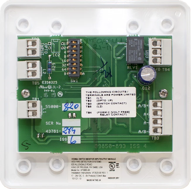
Product overview
The VES VF5665 VES95A input/output monitor combines contact monitoring with a relay operated by the compatible panel software. Its input channels have different supervision characteristics, so the non-supervised input must be assigned only to a permitted function. Confirm the connected contacts, end-of-line arrangement, relay load and cause-and-effect programming as one interface design. The published relay rating is a limit for the stated load conditions, not a general equipment power rating.
Technical specifications
| Brand / product range | VES |
|---|---|
| Product / system | VF5665-00 Input / Output Monitor |
| Product type | Fire Detection |
| Product family | Fire Detection & Alarm |
| Subcategory | Apollo Modules |
| Model | VF5665-00 |
| Functions | Supervised input, non-supervised input and software-controlled single-pole relay output |
| SLC voltage | 17–28 V DC |
| Switch-on surge | 3.5 mA for up to 150 milliseconds |
| Quiescent current | 1.2 mA with 20 kΩ end-of-line resistance fitted |
| Maximum short-circuit input current with LED | 6 mA |
| Other stated LED-on current | 4.5 mA |
| Open-circuit monitoring voltage | 9–11 V DC |
| Maximum cable resistance | 50 Ω |
| Opto-coupled input | Maximum 35 V DC; 10 kΩ impedance |
| Relay contact rating | Maximum 1 A at 30 V AC or DC, inductive or resistive |
| Relay wetting current | 10 µA at 10 mV DC |
| Published temperature range | 68°F to 158°F; confirm current model instructions before use outside this stated range |
| Humidity | Up to 90%, non-condensing |
| Mounting | Two-gang or 4 inch square electrical box |
| Supervision limitation | The non-supervised input must not be assumed to provide supervised fire-alarm initiation |
Key features
- Model: VF5665-00
- Functions: Supervised input, non-supervised input and software-controlled single-pole relay output
- SLC voltage: 17–28 V DC
Applications
Compatible fire alarm and ancillary-equipment interfaces requiring the documented combination of supervised monitoring and a configured relay output. Verify which input functions are permitted for each project duty.
Selection and project integration
Share the fire alarm drawings, equipment schedule, compatible panel platform and cause-and-effect requirements with UDCT. Selection should confirm device protocols, supported interfaces, circuit supervision, power and standby calculations, and the exact enclosure or module arrangement.
Use the current manufacturer documentation to check compatibility, wiring limits, software requirements and approval scope. Commissioning should verify the configured alarm, fault, indication and control functions as part of the complete system. Remote reporting also requires a compatible receiving service and confirmation of local network availability.
Manufacturer documents
Official product reference
View this product on the manufacturer website (opens in a new tab)