
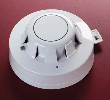
Product overview
The VES VF5670 XP95A photoelectric smoke sensor uses an optical chamber to detect light scattered by smoke particles. Its processed analogue value is transmitted to compatible fire alarm control equipment through the powered two-wire loop. The XPERT card defines the location address at the mounting base. Coordinate the detector and base with the panel, approved sensitivity settings and installation environment; the sensing principle must be selected for the expected fire conditions and required coverage.
Technical specifications
| Brand / product range | VES |
|---|---|
| Product / system | VF5670 XP95A Photoelectric Detector |
| Product type | Fire Detection |
| Product family | Fire Detection & Alarm |
| Subcategory | Apollo Addressable |
| Model | VF5670-00 |
| Detection principle | Infrared light-scatter photoelectric smoke sensing |
| Supply | 17–28 V DC, two-wire loop |
| Quiescent current | 340 µA average / 600 µA peak |
| Power-up surge | 1 mA |
| Alarm LED current | 4 mA |
| Remote indicator | 4 mA at 5 V across the remote load |
| Sampling frequency | Once per second |
| Operating temperature | −4°F to 140°F |
| Humidity | 0–95% without condensation or icing |
| Protection rating | IP23D |
| Dimensions | 3.93 inch diameter x 1.65 inch high; 1.96 inch in base |
| Detector weight | 3.7 oz |
| Addressing | XPERT card with the compatible mounting base |
| Construction | White polycarbonate housing; nickel-plated stainless-steel terminals |
Key features
- Model: VF5670-00
- Detection principle: Infrared light-scatter photoelectric smoke sensing
- Supply: 17–28 V DC, two-wire loop
Applications
Compatible addressable smoke-detection installations where photoelectric sensing is appropriate, including approved sleeping-area and escape-route designs. Establish spacing and response settings using the manufacturer instructions.
Selection and project integration
Share the fire alarm drawings, equipment schedule, compatible panel platform and cause-and-effect requirements with UDCT. Selection should confirm device protocols, supported interfaces, circuit supervision, power and standby calculations, and the exact enclosure or module arrangement.
Use the current manufacturer documentation to check compatibility, wiring limits, software requirements and approval scope. Commissioning should verify the configured alarm, fault, indication and control functions as part of the complete system. Remote reporting also requires a compatible receiving service and confirmation of local network availability.
Manufacturer documents
Official product reference
View this product on the manufacturer website (opens in a new tab)