
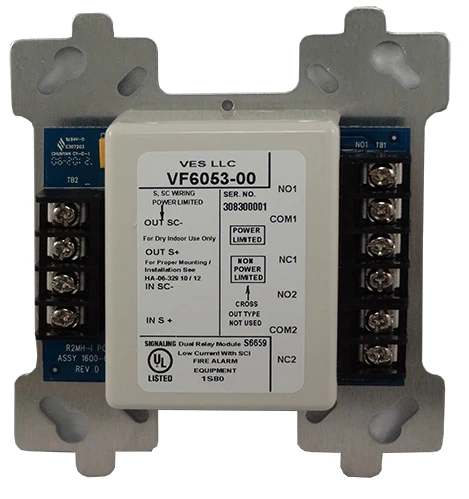
Product overview
The VES VF6052-55 Dual Relay Module provides two independently controlled changeover relay contacts from one SLC address. Its circuit role and electrical limits must be coordinated with the compatible panel and approved fire alarm design. The model-specific data below distinguishes the interface configuration, supply requirements and installation conditions so the exact version can be selected for the project.
Technical specifications
| Manufacturer | VES |
|---|---|
| Product / system | VF6052-55 Dual Relay Module |
| Product type | Fire Detection |
| Product family | Fire Detection & Alarm |
| Subcategory | Addressable Modules |
| Models | VF6052-00 / VF6053-00 / VF6054-00 / VF6055-00 |
| Relay contacts | Two independently controlled Form C contacts per SLC address |
| Low-voltage versions | VF6052 / VF6053: 2 A at 30 V DC; 0.5 A at 120 V AC |
| High-voltage versions | VF6054 / VF6055: 8 A at 30 V DC; 4.8 A at 250 V AC |
| Isolator versions | VF6053 / VF6055 only |
| Nominal supply range | 25.3–39 V DC |
| Typical normal / alarm current | 350 µA / 405 µA |
| Maximum devices per loop | 127 |
| Mounting | 4 inch square electrical box |
| Dimensions W x H x D | 4.2 x 4.7 x 1.4 inches |
| UL installation temperature | 32°F to 120°F |
| Humidity | Up to 90%, non-condensing |
Key features
- Models: VF6052-00 / VF6053-00 / VF6054-00 / VF6055-00
- Relay contacts: Two independently controlled Form C contacts per SLC address
- Low-voltage versions: VF6052 / VF6053: 2 A at 30 V DC; 0.5 A at 120 V AC
Applications
Configured fan, door, elevator recall and auxiliary interface control using contact ratings appropriate to the connected load.
Selection and project integration
Share the fire alarm drawings, equipment schedule, compatible panel platform and cause-and-effect requirements with UDCT. Selection should confirm device protocols, supported interfaces, circuit supervision, power and standby calculations, and the exact enclosure or module arrangement.
Use the current manufacturer documentation to check compatibility, wiring limits, software requirements and approval scope. Commissioning should verify the configured alarm, fault, indication and control functions as part of the complete system. Remote reporting also requires a compatible receiving service and confirmation of local network availability.
Manufacturer documents
Official product reference
View this product on the manufacturer website (opens in a new tab)