
Product overview
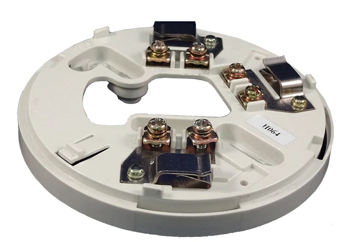
The VES VF7001 / VF7002 4 in / 6 in Analog Bases provides the mounting and electrical connection for the compatible analogue sensor models listed in the technical data. Its electronics-free design uses screw terminals and allows a compatible sensor to be replaced without disturbing the field wiring. Compatibility is limited to the documented detector and panel combinations. Choose the 4 inch or 6 inch version, mounting arrangement and optional tamper-lock feature to suit the installation.
Technical specifications
| Brand / product range | VES |
|---|---|
| Product / system | VF7001 / VF7002 4 in / 6 in Analog Bases |
| Product type | Fire Detection |
| Product family | Fire Detection & Alarm |
| Subcategory | Addressable Initiating Devices |
| Models | VF7001-00: 4 inch / VF7002-00: 6 inch |
| Base type | Electronics-free analogue sensor mounting base |
| Listed sensor references | VF2001, VF2002, VF2003, VF2005, VF2008, VF2010, VF2011, VF2012 |
| Connection | Elite SLC, screw terminals |
| SLC maximum resistance | 50 ohms |
| Security feature | Optional plastic tamper-lock tab |
| Material / colour | Bone PC / ABS blend |
| Manufacturer-listed approvals | UL Listed, compatible detector and panel combination applies |
Approval scope applies to the listed system and component configuration. Confirm the selected equipment against the current manufacturer document and project submittal.
Key features
- Models: VF7001-00: 4 inch / VF7002-00: 6 inch
- Base type: Electronics-free analogue sensor mounting base
- Listed sensor references: VF2001, VF2002, VF2003, VF2005, VF2008, VF2010, VF2011, VF2012
Applications
Mounting and wiring of the specifically listed VES analogue sensors within a compatible fire alarm system. Confirm the exact detector/base combination and enclosure requirements before procurement.
Selection and project integration
Share the fire alarm drawings, equipment schedule, compatible panel platform and cause-and-effect requirements with UDCT. Selection should confirm device protocols, supported interfaces, circuit supervision, power and standby calculations, and the exact enclosure or module arrangement.
Use the current manufacturer documentation to check compatibility, wiring limits, software requirements and approval scope. Commissioning should verify the configured alarm, fault, indication and control functions as part of the complete system. Remote reporting also requires a compatible receiving service and confirmation of local network availability.
Manufacturer documents
Official product reference
View this product on the manufacturer website (opens in a new tab)