
Product overview
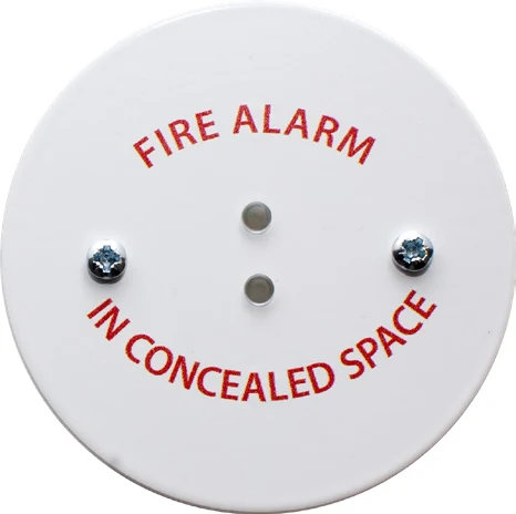
The VES VF8201 and VF8202 extend the indication of a compatible concealed detector to a visible position. Round and square versions use different backbox arrangements and show alternating red LEDs. The remote unit must connect only to the detector or base terminals identified by its manufacturer; an incorrect connection can impair detector operation. Confirm electrical compatibility before selecting the indicator and any ceiling accessory.
Technical specifications
| Brand / product range | VES |
|---|---|
| Product / system | VF8201 / VF8202 Remote Indicator Unit |
| Product type | Fire Detection |
| Product family | Accessories & Power |
| Subcategory | Accessories / Power |
| Models | VF8201-00 round / VF8202-00 square |
| Function | Remote LED indication for a compatible concealed detector |
| Supply | 15–30 V DC |
| Maximum current | 20 mA at 24 V DC |
| Indication | Two red LEDs, alternating flash |
| Mounting | Round: BESA box / square: single-gang electrical backbox |
| Published enclosure dimensions | 3.4 x 3.4 x 1.18 inches; confirm selected shape |
| Enclosure rating | IP40 |
| Finish | White epoxy powder coating |
| Operating temperature | 23°F to 122°F |
| Humidity | Less than 95%, non-condensing |
| Connection condition | Use only the remote-indicator connections specified by the detector/base manufacturer |
Key features
- Models: VF8201-00 round / VF8202-00 square
- Function: Remote LED indication for a compatible concealed detector
- Supply: 15–30 V DC
Applications
Remote indication for compatible detectors in concealed or otherwise difficult-to-observe locations, following the detector/base instructions.
Selection and project integration
Share the fire alarm drawings, equipment schedule, compatible panel platform and cause-and-effect requirements with UDCT. Selection should confirm device protocols, supported interfaces, circuit supervision, power and standby calculations, and the exact enclosure or module arrangement.
Use the current manufacturer documentation to check compatibility, wiring limits, software requirements and approval scope. Commissioning should verify the configured alarm, fault, indication and control functions as part of the complete system. Remote reporting also requires a compatible receiving service and confirmation of local network availability.
Manufacturer documents
Official product reference
View this product on the manufacturer website (opens in a new tab)